Working principle of turbocharger
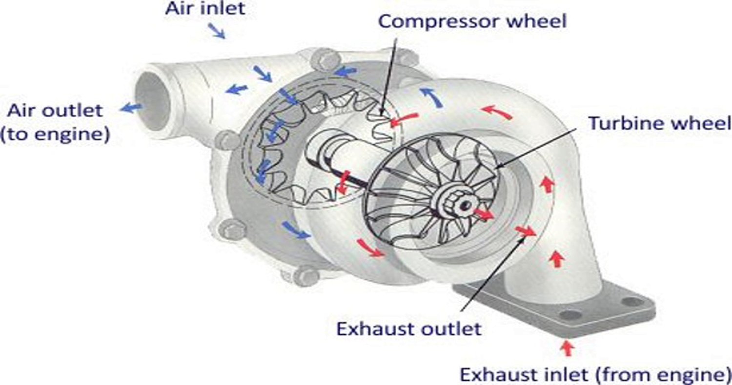
A turbocharger consists of a compressor wheel and exhaust gas turbine wheel coupled together by a solid shaft and that is used to boost the intake air pressure of an internal combustion engine. The exhaust gas turbine extracts energy from the exhaust gas and uses it to drive the compressor and overcome friction. In most automotive-type applications, both the compressor and turbine wheel are of the radial flow type. Some applications, such as medium- and low- speed diesel engines, can use an axial flow turbine wheel instead of a radial flow turbine.
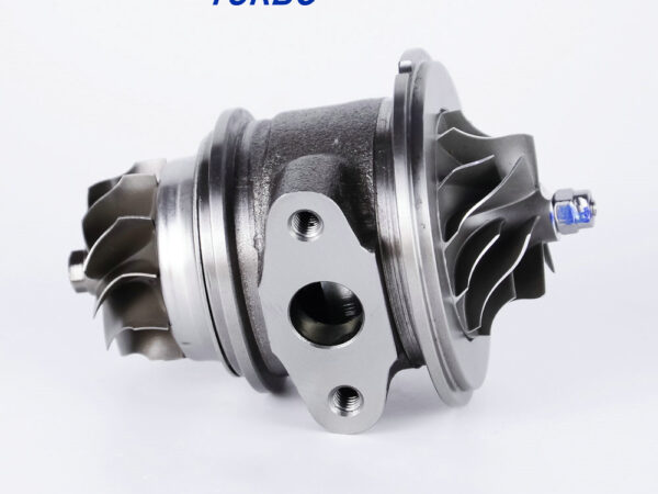
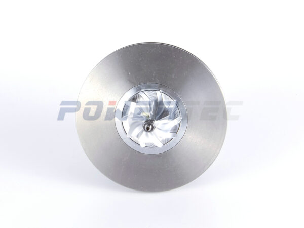
The turbine-compressor common shaft is supported by a bearing system in the center housing (bearing housing) located between the compressor and turbine . The shaft wheel assembly (SWA) refers to the shaft with the compressor and turbine wheels attached, i.e., the rotating assembly. The center housing rotating assembly (CHRA) refers to SWA installed in the center-housing but without the compressor and turbine housings. The center housing is commonly cast from gray cast iron, but aluminum can also be used in some applications. Seals help keep oil from passing through to the compressor and turbine. Turbochargers for high exhaust gas temperature applications, such as spark ignition engines, can also incorporate cooling passages in the center housing.
Turbocharger seals are different from the soft lip seals normally found in rotating equipment operating at much lower speeds and temperatures. The piston ring type seal is one type that is often used. It consists of a metal ring, similar in appearance to a piston ring. The seal remains stationary when the shaft rotates. Labyrinth-type seals are another type sometimes used. Generally, turbocharger shaft seals will not prevent oil leakage if the pressure differential reverses such that the pressure in the center housing is higher than in the intake or exhaust systems.


